Create Space
 Used to draw, locate,
identify, and label individual spaces such as rooms, or logically related
spaces such as departments. Spaces are associative. That is, if a wall is moved
(the graphic space updates) the area measurement updates in the label and the
model data updates for report and schedule purposes. Space associativity is
only available when a space is created using the flood boundary method. Label
placement can be manual or automatic. When placement is automatic, labels are
positioned at the centroid of the room.
Used to draw, locate,
identify, and label individual spaces such as rooms, or logically related
spaces such as departments. Spaces are associative. That is, if a wall is moved
(the graphic space updates) the area measurement updates in the label and the
model data updates for report and schedule purposes. Space associativity is
only available when a space is created using the flood boundary method. Label
placement can be manual or automatic. When placement is automatic, labels are
positioned at the centroid of the room.
Tip: The
Create Space tool can also create
3D spaces using the solids and shapes drawn using the free form tool. The tool
converts these regions into 3D space that are compatible with the Energy
Analysis workflow.
Note:
Placement is completed using the controls found on the
Placement ribbon tab and the
Property Panel which is loaded with the active
Building element catalog items and properties.
Accessed from:
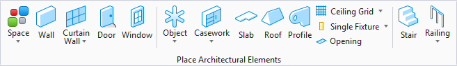
Placement tab
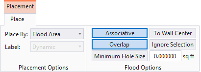
Note:
The
Placement tab opens on the ribbon when placing
Building elements. The
Placement tab contains settings specific to the
Building element being placed that are used to define the position, orientation
or dimensions of the Building element being placed. Also available on the
Placement tab, are a collection of Building
common tools selected specifically because of their relevance to the Building
element being placed.
Space Properties

| Setting | Description |
|---|---|
| Catalog Type Selector | Used to select from available Catalog Types. Selections made here updates the Catalog Item Selector combo box. |
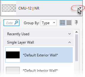
| Catalog Item Selector |
Used to select from available
Catalog Items. The
Catalog Item Selector combo box contains
several options and settings designed to make it easier to find the exact
catalog item you need to place/change.
The
Catalog Item list also includes user
defined assemblies, and RFA catalog items, if any.
|
| Catalog Tools | A split button located to the right of the
Catalog Item Selector contains tools to
assist with managing catalog data prior to placement of selected catalog items.
Note: The
Save Catalog Item and
Save Catalog Item As... tools perform
administrative tasks on DataGroup System catalogs. Administrators and users may
want to hide the tool icons to avoid incidental or unwanted changes to their
firm's dataset by setting the user configuration variables
BB_CATALOGITEM_ADMIN_IN_PLACECMDS
and
BB_CATALOGITEM_SAVEAS_IN_PLACECMDS to "0", respectively.
|
| Preview |
Displays the selected catalog item in the preview
window. This display changes and the preview updates as various options are
chosen. The preview also changes dynamically with some of the
prominent settings on the Placement tab, e.g Height, Rotation angle, etc. A
right-click in the Preview opens a
Show/Hide Viewing Tools option menu:
|
| Properties list - toolbar |
Used to manage catalog item properties during
placement or modification. Catalog item properties define the catalog item
instance in the model, and are accountable in the DataGroup System data
management tools. You can place a catalog item with its default property values
or you can change property values as needed, place an instance in the model,
and optionally save the changes to the catalog.
The Properties combo box contains tools for sorting and searching the properties list:
|
| Space Parameters |
|
| Materials | Lists Part and Family definition assignments. Clicking in the Value column cell opens a Family and Part selection box. Here parts and families are available from the option menus. |
| Energy Analysis |
|
| IFC Override | Lists IFC properties not automatically mapped to DataGroup System properties that can be manipulated for export. |
| Space | Contains space data properties for notes, location, occupancy, finishes, and mechanical and electrical requirements. Data properties can be entered directly in the provided text entry fields or be selected (where available) from predefined drop down menus. Properties are stored on the space component and can be edited with the Modify properties tool and be reported on with the Schedules tool. |
| Discipline | Sets one of the disciplines from pull-down options: Architectural, Structural, Mechanical, and Electrical. |
| Classification | Building Classification Systems are supported by the DataGroup System. MasterFormat, OmniClass, and UniFormat property values can be associated with any Building element. Click the Value cell to open the Classification System selection combo box. The combo box is populated with selected classification system property values. It can be resized by clicking on the combo box's bottom right corner. Search for properties by name. Search results are displayed in the classifications hierarchy. Double click a property to select it. This action also closes the selection menu. The selected property displays in the selected classification system property value (on the Properties list). |
 (
( (
( (
( (
( (
( (
( (
( (
( (
(


 (
( (
( (
(

Note:
Information in the
Value column rows can be completed by selecting
the applicable cell to activate an editor field, an option menu, or a pop up
dialog. This data is written to the element properties. Properties displayed
with grey text are read only. Some of these are set in the placement tool's
Placement tab, and can be modified there. The
dividing bar between the
Property, and
Value columns can be moved to change the width
of either area, or resize the dialog. A vertical and horizontal scroll bars are
available to scroll and adjust
Properties panel viewing and the display of
data.
Note: Decimal point
accuracy for Actual Area and Program area settings values can be controlled by
a user defined configuration variable,
TFANNOTATE_AREAPRECISION. The number of
trailing decimal numbers can be set from 0 to 6, with 2 being the default.
Tip: Spaces
created using the Draw, Select and Flood boundary methods have the default
Label and Area dimensions annotations are displayed in the region as per
currently set Space Type. If the configuration variable
BB_SPACES_NOARTIFACT is set (for Space
Artifact), these annotations will not be seen in the model.